Page 72 - 捷運技術 第35期
P. 72

64  Tomonori Umebayashi  Toshinori Kimura  Hiroyuki Morimoto  陳立島  CRASHWORTHINESS ANALYSIS OF CK371

                                0                                 500

                              -500                      A01-A02   400                       A01-A02
                                                                                            A02-A03
                              -1000                     A02-A03   300                       A03-A04
                                                        A03-A04                             A04-A05
                             Force (KN)  -1500          A04-A05  Deformation of Fuse (excluding coupler  deformation:mm)  200  A05-A06
                                                        A05-A06
                                                                                            A06-B01
                              -2000                     A06-B01   100                       B01-B02
                                                        B01-B02
                                                                                            B02-B03
                                                        B02-B03
                              -2500                                                         B03-B04
                                                        B03-B04    0                        B04-B05
                              -3000                     B04-B05  -100                       B05-B06
                                                        B05-B06
                              -3500                              -200
                                0.00  0.50  1.00 Time (sec) 1.50  2.00  2.50  0.00  0.50  1.00  1.50  2.00  2.50
                                                                               Time (sec)
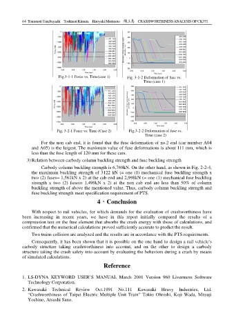
                               Fig.3-1-1 Force vs. Time(case 1)   Fig. 3-1-2 Deformation of fuse vs.
                                   Force vs. Time between each cars (Case 1) (W1+W4)
                                                                        Deformation of Fuse vs. Time (Case 1) (,W1+W4)

                                                                          Time (case 1)
                               0                                    500                     A01-A02
                              -500                      A01-A02     400                     A02-A03
                                                                                            A03-A04
                              -1000                     A02-A03     300                     A04-A05
                                                        A03-A04
                                                        A04-A05     200                     A05-A06
                                                                                            A06-B01
                             Force (KN)  -1500          A05-A06   Deformation of Fuse (excluding coupler  deformation:mm)  100  B01-B02
                                                        A06-B01
                                                                                            B02-B03
                                                        B01-B02
                              -2000
                                                                                            B03-B04
                              -2500                     B02-B03    -100 0                   B04-B05
                                                        B03-B04
                                                                                            B05-B06
                                                        B04-B05
                                                        B05-B06    -200
                              -3000
                              -3500                                -300 0.00  0.50  1.00  1.50  2.00  2.50
                                0.00  0.50  1.00  1.50  2.00  2.50
                                            Time (sec)                           Time (sec)
                                                                        Deformation of Fuse vs. Time (Case 2) (,W4+W4)
                                   Force vs. Time between each cars (Case 2) (W4+W4)
                              Fig. 3-2-1 Force vs. Time (Case 2)   Fig.3-2-2 Deformation of fuse vs.
                                                                           Time (case 2)
                      For the non cab end, it is found that the fuse deformation of no.2 end (car number A04
                 and A05) is the largest. The maximum value of fuse deformations is about 111 mm, which is
                 less than the fuse length of 120 mm for these cars.
               3) Relation between carbody column buckling strength and fuse buckling strength
                      Carbody column buckling strength is 6,769kN. On the other hand, as shown in Fig. 2-2-4,
                 the maximum buckling strength of 3122 kN (= one (1) mechanical fuse buckling strength x
                 two (2) fuses= 1,561kN x 2) at the cab end and 2,998kN (= one (1) mechanical fuse buckling
                 strength x two (2) fuses= 1,499kN x 2) at the non cab end are less than 50% of column
                 buckling strength of above the mentioned value. Thus, carbody column buckling strength and
                 fuse buckling strength meet specification requirement of PTS.
                                                  4、Conclusion
                 With respect to rail vehicles, for which demands for the evaluation of crashworthiness have
            been increasing in recent years, we have in this report initially compared the results of a
            compression test on the fuse element that absorbs the crash energy with those of calculations, and
            confirmed that the numerical calculations proved sufficiently accurate to predict the result.
                 Two trains collision are analyzed and the results are in accordance with the PTS requirements.
                 Consequently, it has been shown that it is possible on the one hand to design a rail vehicle’s
            carbody structure taking crashworthiness into  account, and on the other to design a carbody
            structure taking the crash safety into account by evaluating the behaviors during a crash by means
            of simulated calculations.
                                                      Reference


            1.  LS-DYNA KEYWORD USER’S MANUAL March 2001 Version 960 Livermore Software
               Technology Corporation.
            2.  Kawasaki Technical Review Oct.1991 No.111 Kawasaki Heavy Industries, Ltd.
               “Crashworthiness of Taipei Electric Multiple Unit Train” Tokio Ohnishi, Koji Wada, Mitsuji
               Yoshino, Atsushi Sano.
   67   68   69   70   71   72   73   74   75   76   77