
Page 69 - 捷運技術 第35期
P. 69
捷運技術半年刊 第 35 期 95 年 8 月 61
2.2 2.2 Load-Deformation Curve
The springs used in this analysis have non-linear characteristics, i.e., a non-linear load
deformation curve (P-δcurve). Characteristics of coupler-fuse-carbody system is obtained
from the below items 1), 2) and 3).
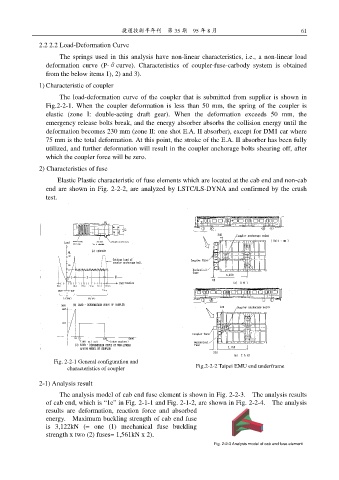
1) Characteristic of coupler
The load-deformation curve of the coupler that is submitted from supplier is shown in
Fig.2-2-1. When the coupler deformation is less than 50 mm, the spring of the coupler is
elastic (zone I: double-acting draft gear). When the deformation exceeds 50 mm, the
emergency release bolts break, and the energy absorber absorbs the collision energy until the
deformation becomes 230 mm (zone II: one shot E.A. II absorber), except for DM1 car where
75 mm is the total deformation. At this point, the stroke of the E.A. II absorber has been fully
utilized, and further deformation will result in the coupler anchorage bolts shearing off, after
which the coupler force will be zero.
2) Characteristics of fuse
Elastic Plastic characteristic of fuse elements which are located at the cab end and non-cab
end are shown in Fig. 2-2-2, are analyzed by LSTC/LS-DYNA and confirmed by the crush
test.
Fig. 2-2-1 General configuration and
fi
F 圖 characteristics of coupler ti Fig.2-2-2 Taipei EMU end underframe
l
2 4 G
2-1) Analysis result
The analysis model of cab end fuse element is shown in Fig. 2-2-3. The analysis results
of cab end, which is “1e” in Fig. 2-1-1 and Fig. 2-1-2, are shown in Fig. 2-2-4. The analysis
results are deformation, reaction force and absorbed
energy. Maximum buckling strength of cab end fuse
is 3,122kN (= one (1) mechanical fuse buckling
strength x two (2) fuses= 1,561kN x 2).
Fig. 2-2-3 Analysis model of cab end fuse element