
Page 71 - 捷運技術 第35期
P. 71
捷運技術半年刊 第 35 期 95 年 8 月 63
3) Characteristics of carbody
The carbody column buckling strength of the car body which is obtained from static
analysis results by using MSC/NASTRAN is 6,769kN.
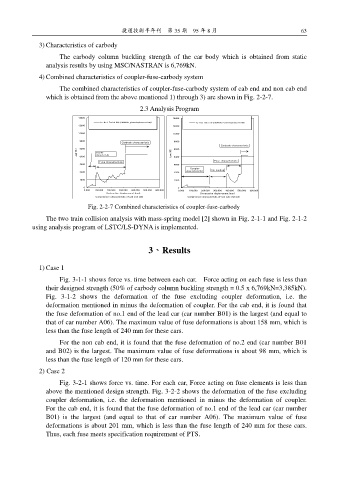
4) Combined characteristics of coupler-fuse-carbody system
The combined characteristics of coupler-fuse-carbody system of cab end and non cab end
which is obtained from the above mentioned 1) through 3) are shown in Fig. 2-2-7.
2.3 Analysis Program
14400 14400
12800 1e:No.1 End of DM (SMA490、plate thickness t8+t6) 12800 2c:Non Cab End (SMA490, Plate thickness t8+t6)
11200 11200
9600 9600
Carbody characteristic
8000 8000 Carbody characteristic
Load (KN) Coupler Load (KN)
characteristic
6400 Fuse characteristic 6400 Fuse characteristic
4800 4800
Coupler
3200 3200 characterictic No loading
1600 1600
0 0
0.000 100.000 200.000 300.000 400.000 500.000 600.000 0.000 100.000 200.000 300.000 400.000 500.000 600.000
Compressive characteristic of cab end side Compressive characteristic of non cab end side
Destructive displacement (mm)
Destructive displacement (mm)
Fig. 2-2-7 Combined characteristics of coupler-fuse-carbody
The two train collision analysis with mass-spring model [2] shown in Fig. 2-1-1 and Fig. 2-1-2
using analysis program of LSTC/LS-DYNA is implemented.
3、Results
1) Case 1
Fig. 3-1-1 shows force vs. time between each car. Force acting on each fuse is less than
their designed strength (50% of carbody column buckling strength = 0.5 x 6,769kN=3,385kN).
Fig. 3-1-2 shows the deformation of the fuse excluding coupler deformation, i.e. the
deformation mentioned in minus the deformation of coupler. For the cab end, it is found that
the fuse deformation of no.1 end of the lead car (car number B01) is the largest (and equal to
that of car number A06). The maximum value of fuse deformations is about 158 mm, which is
less than the fuse length of 240 mm for these cars.
For the non cab end, it is found that the fuse deformation of no.2 end (car number B01
and B02) is the largest. The maximum value of fuse deformations is about 98 mm, which is
less than the fuse length of 120 mm for these cars.
2) Case 2
Fig. 3-2-1 shows force vs. time. For each car, Force acting on fuse elements is less than
above the mentioned design strength. Fig. 3-2-2 shows the deformation of the fuse excluding
coupler deformation, i.e. the deformation mentioned in minus the deformation of coupler.
For the cab end, it is found that the fuse deformation of no.1 end of the lead car (car number
B01) is the largest (and equal to that of car number A06). The maximum value of fuse
deformations is about 201 mm, which is less than the fuse length of 240 mm for these cars.
Thus, each fuse meets specification requirement of PTS.