
Page 262 - 捷運工程叢書 精進版 - 32 捷運高架橋梁結構設計與施工
P. 262
臺北市政府捷運工程局
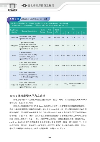
表 10-5-11 Values of Coefficient for Rock
Nms for Estimation the Ultimate Bearing Capacity on Broken or Jointed Rock
(Modified after Hoek,(1993))(摘自 AASHTO(2002)TABLE 4.4.8.1.2A)
Rock Mass General Description RMR NGI RQD N ms
Quality Rating Rating (%) A B C D E
Intact rock with joints
Excellent 100 500 95-100 3.8 4.3 5.0 5.2 6.1
spaced >10 feet apart
Tightly interlocking ,
undisturbed rock with
Very good 85 100 90-95 1.4 1.6 1.9 2.0 2.3
rough unweathered joints
spaced 3 to 10 feet apart
Fresh to slightly
weathered rock, slightly
Good 65 10 75-90 0.28 0.32 0.38 0.40 0.46
disturbed with joints
spaced 3 to 10 feet apart
Rock with several sets
of moderately weathered
Fair 44 1 50-75 0.049 0.056 0.066 0.069 0.081
joints spaced 1 to 3 feet
apart
Rock with numerous
weathered joints spaced
Poor 23 0.1 25-50 0.015 0.016 0.019 0.02 0.024
1 to 20 inches apart with
some gouge
Rock with numerous
Very poor highly weathered joints 3 0.01 ﹤25 Use q ult for an equivalent soil
spaced ﹤2 inches apart mass
10.5.5 基樁承受水平力之分析
群樁基礎承受水平力作用所產生之側向位移、剪力、彎矩,採用群樁程式 GROUP 6.0
進行分析,如圖 10-5-2 所示。
本程式由美國奧斯汀德州大學 Reese 教授等人所研發,根據實際側向樁載重試驗資料,
提出土壤非線性關係之基樁側向荷重-變位曲線(p-y 曲線)法,配合彈性基礎梁理論及電
腦數值解析,可分析群樁樁帽承受三維(共 6 個自由度)外來荷重的情況分配至各單獨樁的
分布情形,如圖 10-5-3 所示。程式可依據基樁間距及配置,自動考慮受側向力作用時之群樁
效應(或由工程師自行考量),將 p-y 曲線中之 p 值乘以一適當係數加以折減。進而採用 t-z、
q-z 及 p-y 曲線法計算在不同載重組合及樁頭束制條件(固定、鉸接、彈性束制)下,分析
群樁於不同土層分布、基樁型式、配置及外力狀況下之側向行為,獲得各樁之變形、剪力、
彎矩及土壤抵抗力分布等設計所需之分析結果,如圖 10-5-4 所示。
244 245