
Page 90 - 捷運技術 第35期
P. 90
82 Jeffrey S. Stover CITYFLO 650 System Overview
to three years.
Most recently, Madrid Metro(Spain)has endorsed the CITYFLO solution as its preferred
choice for the ATC upgrade of two of its most important lines, lines 1 and 6, which carry more than
200 million passengers every year.
2、CITYFLO 650:Functional Description
The purpose of this section is to provide an overview of CITYFLO 650 train control system,
including basic concepts and definitions necessary to understand the terms “Moving Block”,
“Communications-Based Train Control System”, the CITYFLO 650 system architecture and some
information about CITYFLO 650 system availability.
2.1 Moving Block Concept
Unlike the traditional “fixed-block” systems, in which the train occupancy is generated by
occupancy of a fixed-length track circuit(or axle counter)section(referred to as a block), in a
“moving-block” system, the “occupancy” of the train moves along with the train in a continuous
fashion and that the length of the block deemed occupied by the train also depends on the speed of
the train.
2.2 Communication-Based Train Control
In a “Communications-Based Train Control” system, the information controlling the train is
transmitted between the train and wayside computers through a radio link, capable of bi-directional
transmission. CITYFLO 650 is a “contact-less” system, which requires neither track circuits nor an
on-board operator to provide a completely automated operation.
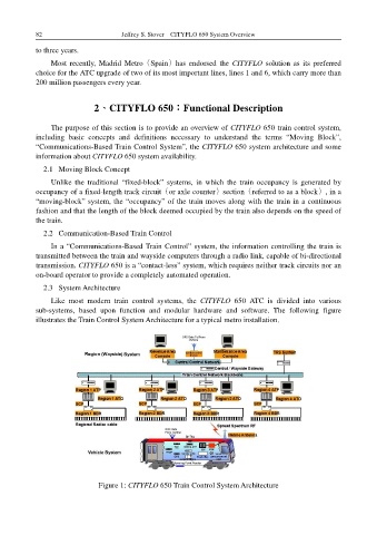
2.3 System Architecture
Like most modern train control systems, the CITYFLO 650 ATC is divided into various
sub-systems, based upon function and modular hardware and software. The following figure
illustrates the Train Control System Architecture for a typical metro installation.
Figure 1: CITYFLO 650 Train Control System Architecture