
Page 91 - 捷運技術 第35期
P. 91
捷運技術半年刊 第 35 期 95 年 8 月 83
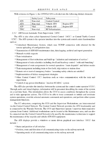
With reference to Figure 1, the CITYFLO 650 is divided into the following distinct elements:
Safety Level Subsystem
ATS Non-vital Central Control
ATO Non-vital Vehicle ATO Region ATO
ATP Vital Vehicle ATP Region ATP
TWC Non-vital RF Infrastructure
2.3.1 EBI Screen Automatic Train Supervision(ATS)
The ATS is also often called Operational Central Control(OCC)or Central Traffic Control
(CTC). The ATS system is the operator interface into the system and control centre functionalities
such as:
˙Centralized Maintenance System, which uses TCP/IP connection with ethernet for the
remote uploading of configuration data
˙Transmission of ATP/ATO maintenance data, data logging, archival and report generation
˙Manual override requests
˙Train initialization
˙Management of fleet reductions and build-up(initiation and termination of service)
˙Management of train schedules including dwell and headway control(with anti-bunching)
˙Management of route assignments for normal operations(train dispatch)and failure modes
˙Train management including train or fleet hold, skip station or station close
˙Remote set or reset of emergency brakes(assuming safety criteria are satisfied)
˙Implementation of failure management strategies
˙Other Central Control(CC)functions such as voice communication with the train and
supervision
˙Control of any power distribution(traction SCADA)system
The ATS also provides the interface between the system and the control centre operator(CCO).
Through audio and visual displays, information will be presented describing the status of the system
on a real-time basis. This information allows the CCO to assess conditions throughout the system
and to take appropriate actions. The CCO is be able to issue commands to initiate and terminate
system operations, override selected automatic commands and operations, and perform other system
management functions.
The CC subsystem, comprising the CCO and the Supervisor Workstations, are interconnected
via the Central Control Network. The Central Control Network provides the ATS functionality and
is connected to the Wayside Network. The CCO and Supervisor operate / supervise their respective
systems from Central. Additional workstations can be located at the Maintenance area, and can also
be connected into the Central Control Network to be used by the maintenance technicians to support
the maintenance of the wayside and vehicle ATP/ATO equipment.
The ATS displays provide a windows or menu driven graphical user interface(GUI)that
include:
˙Status and position of all switches
˙Position, route and direction of all communicating trains on the railway network
˙Operating mode of all communicating trains on the railway network