
Page 95 - 捷運技術 第35期
P. 95
捷運技術半年刊 第 35 期 95 年 8 月 87
The TWC not only supports the transfer of train control data between trains and wayside but
also supports the two-way transfer of ATP/ATO maintenance data between the trains and the
Centralized Maintenance Office.
The radio connection is achieved through the use of base data radios(BDRs)and mobile data
radios(MDRs). These spread spectrum radios have been designed to meet the unique demands of
CBTC systems. The BDR and MDR operate at 2.4-GHz to 2.4835-GHz. This can also be adapted to
suit specific requirements or standards associated with non-licensed low power transmission in the
2.4GHz or higher frequency bands per the national legislation adopted within the ITU
recommendations.
The RF-to-fiber conversion units, "EoCell", are used to distribute the radio signal to
wayside-mounted leaky coaxial cable or LOS antennas. The EoCell devices have no oscillators, and
are therefore not an intentional emitter. The power levels into the wayside leaky coaxial cable or
LOS antennas are adjustable at the remote EoCell equipment.
A Base Data Radio(BDR)is co-located with each Region ATP;one for the Master and one for
the Standby. Each BDR(both primary and standby)feeds into a switch and then to a pair of
RF-to-Fiber Master converters(A&B). These fan out(in a star arrangement)to "Remote
RF-to-Fiber Cells" or amplifiers along that Region. The RF system operates in full-duplex mode.
Master A communicates through every odd cell(e.g. A1, A2, A3 etc.), and Master B
communicates through even cells(B1, B2, B3 etc.). Each leaky coaxial cable segment is terminated
by an odd cell and an even cell; therefore if one of the Masters or cells fails, then radio coverage is
maintained.
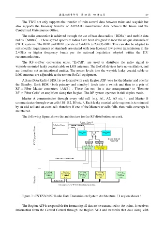
The following figure shows the architecture for the RF distribution network.
Figure 3: CITYFLO 650 Radio Data Transmission System Architecture(1 region shown)
The Region ATP is responsible for formatting all data to be transmitted to the trains. It receives
information from the Central Control through the Region ATO and transmits that data along with